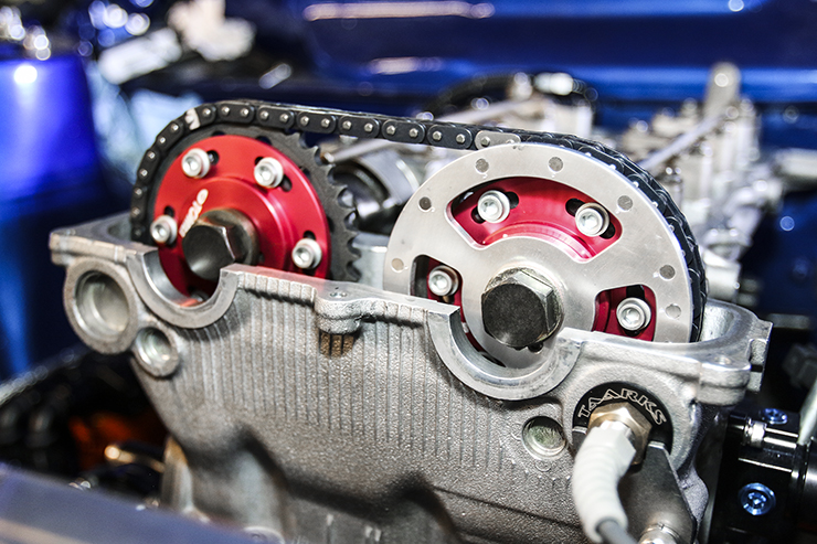
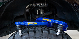
Halloween couldn’t have come any sooner as I’ve been busy turning wrenches and assembling my very own Frankenstein engine, assembled using a slew of parts sourced from a variety of sources – Nissan to Honda. As I sit here plugging away at my keyboard, I find myself reminiscing back to the golden years of import tuning and the LS VTEC hybrid swaps I found myself building back my in youthful days. It was two years ago that I was intrigued to build another hybrid engine, but this time associated with the Nissan branding that best suits my retro-mod Datsun 510.
Head Games
For this particular engine, I’ve made the choice to use a NEO VE cylinder head. You may be wondering what a NEO VE head is, why it’s better than the SR20DE and SR20DET cylinder head, and if it’s any different when compared to Nissan’s VCT (variable cam timing) system. VVL – which stands for Variable Valve Lift – is one of Nissan’s attempts to improve engine efficiency and performance. It does what the Nissan SR20DET-equipped VCT (variable cam timing) system can’t do. I’m going out on a limb here and stating that this cylinder head, when compared to its brethren is superior in every way with respect to port design, performance and efficiency.
The VVL system varies cam lift and duration through the use of hydraulic pressure, which allows the engine to switch between two different sets of camshaft lobes during operation, depending upon which is best suited for the particular conditions. Think of the VVL system as Nissan’s answer to Honda’s VTEC system. The smaller primary lobes are designed for efficiency, lower RPM torque and drivability, while the larger secondary lobes deliver a much more aggressive camshaft profile best suited to making power in the higher rpm range.
Why a NEO VE head?
Nissan utilized the NEO VVL technology to boost power output on its smaller-capacity engines commonly found in the JDM-version Primera, using what’s known as the P11 cylinder head variant and has a power output of 187 horsepower. Nissan also offered three other versions, including the latest P12 version known as the 20V which featured a higher-flowing cylinder head, coil over plugs, larger spec cams, and a CAS (Crank Angle Sensor).
Other models using this technology include the SR20VET/XTrail turbo model. This engine configuration basically uses a P12 cylinder head with VVL on the intake side only. Additionally, the SR16VE/N1 combination is based on the P11 head, but uses a larger intake design and more aggressive cam profile to go with a bump in compression. Unfortunately the N1 model is extremely rare, and P12 heads are priced much higher than the P11 heads, which can quickly wreck the budget. Make no mistake, although the P11 non-N1 version head is the cheapest of the bunch, it does require some additional cash to permit it to be suitable for a rear-wheel-drive conversion, in comparison to simply retaining the SR20DE/DET cylinder head.
How VVL works

Oil pressure activates the individual VVL intake and exhaust solenoids at a pre-determined RPM level to open a passageway down the length of the hollow rocker arm dowel, which in turn spans the rocker arm. Each rocker arm is mounted to a shaft; oil is delivered to it via the hole inside the bore of the rocker arm. As oil pressure builds up, it triggers the VVL activation pin which drives it outwards. When the pin moves outwards, it pivots a mechanism which locks in place underneath the high lobe portion of the rocker arm to increase valve lift.

The improved efficiency reaps benefits in terms of air flow, as the VE head flows a great deal more air than the DE/DET head. Neo VVL engines can generally rev to around 8,200 rpm in stock form; this provides the best of both worlds – great idle response combined with high-rpm power. One of the best parts about converting to a VE head is moving away from the floating rocker setup used with the DE heads; these are notorious for breaking or spitting out at high rpm levels. The VE rockers pivot off a dowel and will never separate or break, which makes them much more reliable even under heavy boost or high RPM use. So what’s not to love about the VVL cylinder head? With a good port and polish job, the SR20VE head can yield flow numbers in the same neighborhood as a ported Honda K-series head.
One Man’s Junk is Another Man’s Treasure
My initial journey began by tracking down both a SR20DET block and SR20VE cylinder head. The search for a used S14 SR20DET block in good condition led me to a friend, who by chance had a surplus of engines he needed to clear from his garage. The long-block looked good upon initial inspection and was sold to me with a S15 6-speed transmission for a rock bottom price. Chris Ankor of Ichiban JDM also came to the rescue and offered a complete P11 SR20VE engine at a killer price that was delivered to my front doorstep in less than 24 hours.

Upon purchasing the S14 long block, I began immediately tearing down the engine. It was during that time when I noticed a major red flag. The previous owner who sold my friend the engine had used silicone gasket sealant to seal the head gasket. The biggest fear was that silicone was used as a band aid to remedy either a warped head or damaged block.
Regardless of the situation, I pressed on and stripped the block bare, knowing that this issue would have to be thoroughly inspected at the machine shop. I also found the crankshaft had some scratches and scoring on the main and rod journals that would also need to be corrected and polished prior to its return to service. Luckily, the internals of the SR20VE engine showed no signs of destruction, as all the parts appeared to be in pristine condition.
Honda Power
Now this is where things get interesting for the build. I decided to integrate a set of Eagle ESP connecting rods designed for the Honda Prelude H22 engine.
Call it blasphemous or just plain awesome, but this is truly a Frankenstein build that is different from a typical SRVE swap. The H22 rods measured in at 5.630-inches long, versus the stock SR20 connecting rod’s length of 5.365-inches, which gives the engine a bump in rod length.
This sets the engine up with a rod-to-stroke ratio of 1.66:1 compared to the stock 1.58:1 ratio. Comparing both Nissan and Honda rods reveals both the big end and small ends are identical in size. The only difference was the rod width which was easily addressed through machining the big ends of the rods to clear the SR20DET crankshaft journals. This gives the engine a better rod ratio without having to shelling out large amounts of cash for a custom set of connecting rods.

The Eagle ESP rods for this build are manufactured using 4340 chromoly steel and weigh in 125 grams per rod lighter than the factory SR20DET rods. In theory, the longer connecting rods should net the engine a wider powerband, while the lighter piston and rod combination will offer improved engine response.
JE Pistons Asymmetrical vs. Round Design Pistons
These JE Pistons asymmetrical forged 2618 pistons utilizes different-sized piston skirts on the major and minor thrust surfaces, giving it the “asymmetrical” piston design. Asymmetrical piston designs can be found in many professional-level racing engines competing in Formula 1, ALMS, and NASCAR; the concept was kept secret until JE began designing the first aftermarket asymmetrical forging in 2010.

Both the asymmetrical piston and “full round” – otherwise known as standard piston designs – are available for most popular applications. In general, both pistons will perform their function in any application if designed properly. However, the asymmetrical piston design has a significant advantage over traditional round designs, including reduced skirt width on the minor thrust side. This helps to minimize piston contact with the cylinder wall, which causes friction and power loss. The design also uses a shorter wristpin that reduces overall weight and internal/external bracing to provide more rigid construction. The sum of these three design elements becomes a significant weight reduction.

For this engine build, I chose an 87 mm piston with an 11.5 to 1 compression ratio. The pistons were spec’d out for the Honda H22 rods, which required a shorter pin height to accommodate the longer rod length. The pistons were also designed specifically for use with the VE cylinder heads, and machined with the requested valve relief depth to clear the soon-to-be-installed Kelford camshafts. I also requested JE’s Tuff Skirt coating and 3D undercrown milling to remove any unnecessary weight. Each of these features will help engine performance in some way.
Cylinder Boring/Honing/Resurfacing
Reputable machine shops will go to great lengths when boring and honing an engine block in order to simulate the same internal stresses the block is under while the engine is operating. This includes bolting on components that stress the block (torque plate, water pump, head studs, etc.) in its assembled and torqued state. Knowing how important it is to find a competent machinist, I commissioned Swedish engine guru extraordinaire Magnus Ohlaker, who previously worked at Cosworth for over 20 years, before acquiring the head machinist position at Hard Media Inc. With experience in Champ Car and Formula 1 engine programs, this guy knows a thing or two about building engines.

Ohlaker carefully took measurements, including piston-to-cylinder wall clearance, before firing up the RMC V40 four-axis CNC engine machine center. The block was bored .020-inch over using a torque plate and with the studs and type of head gasket that will be used in the final assembly of the engine. This assures that the cylinder block is honed properly.
Torquing the head gasket in place using these ARP head studs during the boring/honing of the block will apply a certain amount of un-even pressure on the cylinder walls, which distorts the final round dimension the machinist wishes to achieve.
How important is it to use a torque plate? Out of curiosity, I previously requested a machine shop measure the bore distortion with and without the torque plate on a Nissan KA24DE block. At the time, the machinist measured almost 0.001-inch difference, which may seem inconsequential, but in the world of racing that fraction of an inch means everything.
It’s always safer to run more piston-to-cylinder wall clearance than less, especially if your bores are not perfect. After torquing the crankshaft mains with ARP main studs, Ohlaker line-honed them, decked the block and front cover and inspected the crank before I sent it off to the machinist for micro polishing and balancing.
Balancing Act
When it came time to machine and balance the rotating assembly, I contacted Larry Revis of Revco Precision, located in Long Beach, CA. Revco does everything from polishing, balancing, and knife edging to straightening, strengthening, and machining crankshafts – and does it all within a reasonable price.

In comparison to the factory SR20DET rod, the H22 Honda rod width was measured at 0.937-inch wide vs the SR20’s 0.893-inch-wide dimension. Revco machined each side of the rod’s big end down by 0.022-inch to perfectly clear the crank journals. Machining the rods still allowed the use of a set of H22 undersized ACL rod bearings without any clearance issues.
Using a connecting rod balance scale, Revis carefully weighed each rod. This specialized scale is accurate up to 4,000 grams and has the ability to check weight on both big and small ends of the rod. Weighing a connecting rod using this type of scale will determine how much weight to remove and from which side of the rod to achieve the correct balance of the rotating assembly components. A perfectly balanced rod is a key component inside an engine spinning at 8,000 rpm. Revco also removed excess material from all four pistons for perfect weight balance. Also notice in the photo the JE Pistons 3D undercrown milling treatment.
Revco Precision checks for crankshaft straightness, performing a simple technique of stress relieving the metal while straightening out the crankshaft to allowable tolerances.
“A lot of guys won’t do the stress relief, and they wonder why their crankshafts crack prematurely,” Revis says.
In performance applications such as our VE/DET, he works to achieve crankshaft balance to within 0.1 thousandths of a gram. Too often I hear the horror stories of improperly balanced factory and aftermarket crankshafts breaking into pieces and ruining a perfectly good engine.
Revco removed material from our Spec flywheel and clutch cover to balance our assembly.

Oiling Upgrade
The oil pump from the DE/DET engine is not ideal to use with the VE head as each of these particular oil pumps don’t provide enough consistent high oil pressure, which the VE engine requires to activate both VVL solenoids.
When assembling a hybrid setup using these components, a VE oil pump and front cover should be used. When using the VVL spacer the pulleys will be about .25-inch behind the crank pulley. To remedy this issue, either space out all the accessory pulleys to align correctly or request the machine shop to remove 3 mm from the pump snout. A VE oil pump spacer/pump driver needs to be used, as it is longer in order to perfectly align all the pulleys. It is also important to use the VE oil drive collar instead of the SR20DET unit or else the oil pump housing will crack when tightening the crank pulley – that’s not a good thing.

When installing the VVL oil pump housing, it’s highly suggested to have the machine shop deck the block with the new VVL front cover mounted, as the height of the cover is slightly shorter than the DET block. Neglecting to machine both parts to will cause an uneven mating surface for the head gasket which will eventually lead to leaks or a blown head gasket.

Due to mixing and matching the VVL FWD and SR20DET RWD conversion parts, the timing marks will not align correctly with the VVL oil pump when using the RWD crank pulley. When using the VVL front cover, the timing pin is shorter, so it places the marks on the opposite side of the RWD pulley. To remedy this problem, I turned to the Nissan SR20VE/NEO VVL swap parts specialists known as Taarks, located in Australia. Taarks offers a number of items including a timing pin locator kit to address this issue, which brings the marks back to the correct RWD location.

The cylinder head oil drain located towards the rear of the block on the intake side on the SR20DET engine needs to be plugged to prevent oil flow. There are several ways to address this. The first is to install an aluminum bung that is sold by various VVL conversion manufacturers. The second is to weld up the hole and have the block decked. The third is to drill and tap the hole and using an Allen plug to seal the hole.
I selected option 3 as it provided the simplest, most cost effective method that could easily be reversed if for any reason I decided to go back to using the original SR20DET head. The block also required plugging the S14 SR20DET VTC feed hole located towards the front of the block. Some head gaskets don’t come with material around the VCT feed at the front driver’s side of the block. If this hole isn’t blocked off or head gasket material doesn’t surround it, a massive oil leak occurs.

It was a no-brainer to upgrade to a multi-layer steel gasket. The OEM gasket is comprised of a composite material that is inherently weak in high performance builds. Most engine builders simply install a SR20VET multi-layer gasket and call it a day, but I decided to take things one step further and use a Tomei Powered 1.2mm head gasket.

All Tomei metal head gaskets are made from a triple layer, super grommet design. Installing the gasket required us to modify the piece by slightly cutting and grinding the area where the front cover and cylinder head meet due to using the VVL front cover. Since this was an area of the gasket that wasn’t witnessing a large area of clamping force, the necessary modifications were deemed harmless to the engine’s performance. I should also note that the pistons were specifically designed by JE for the 1.2mm head gasket thickness to achieve the target 11.5:1 compression ratio.
A new OEM factory water pump was installed in conjunction with an Oka-chan Super Water Pump Pulley from Yashio Factory. The lightweight, anodized (yes, I know it’s pink!) aluminum construction is 10 percent larger than OEM and designed to reduce rotational mass, which helps to increase the life of the water pump and improve cooling efficiency. SR engines are notorious for suffering overheating issues at higher rpms; this is caused by the stock water pump pulley’s rotational speed, which causes water pump cavitation and air pockets in the cooling system. The new pump and pulley should remedy this situation.
Assembly Process
With the bottom end machined and refreshed, we began the process of assembling the bottom end. Shingo Yugami of Bluemoon Performance measured the rod and main bearings for proper clearances. We finalized the ACL rod and main bearings with clearances a tad bit on the looser side, sufficient enough for my plans of taking the car to the track on the weekends.
Yugami also took measurements of each cylinder and ring; he then worked to achieve proper piston ring gap for this application.
Piston ring end gap provides the necessary room for rings to grow when exposed to heat. Because every engine is different, the proper ring end gap varies for each application. Variables such as power output, bore size, ring material, and more can change the required gap. Insufficient ring end gap will lead to contact between the ends of the rings, which causes damage to the rings, cylinder walls, and pistons, and can potentially destroy an engine.
If the ring gap is too large, the ring will not effectively control the combustion chamber’s blow-by gasses and cause a loss in power.
| JE Pistons Recommended Ring Gap | Minimum Gap per Inch of Bore | ||
| Top Ring | Second Ring | Oil Ring Rail | |
| Vehicle Application | Bore size x | Bore size x | Min. Gap |
| High-Performance NA Street/Strip | .0045 inch | .0050 inch | .0015 inch |
| Moderate Turbo/Nitrous | .0050 inch | .0055 inch | .0015 inch |
| High-Power Street Turbo/Nitrous | .0055 inch | .0057 inch | .0015 inch |
| Turbo/Nitrous Race Only | .0060 inch | .0063 inch | .0015 inch |
OEM vs. Aftermarket Bearing
New crankshaft and rod bearings are a must when rebuilding an engine, but not all bearings are created equal. Factory bearings are usually made of weak alloys that don’t tolerate much abuse nor high oil temperatures. In fact, many factory engine bearings can start delaminating once they reach a temperature of as little as 230 degrees Fahrenheit during sustained use.

Tri-metal or quad-metal bearings like the ones for this engine from ACL have far greater wear resistance properties and can withstand higher engine loads for extended periods when compared to OEM bearings. Steel-backed bearings layered with tri- or quad-layered alloys are designed to handle severe forces from high boost and/or high horsepower. Many OEM manufacturers have shifted to using aluminum bearings in today’s vehicles, which is easily recyclable and good for the environment, but less than ideal when used in racing or high-horsepower applications due to their fragile construction.

When removing old bearings, inspect them for unusual wear or damage such as scoring, wiping, and dirt or debris embedded in the surface. Inadequate oil cooling is also a cause of many high-boost engine failures on street and road race cars. Anything other than normal wear may indicate an underlying problem that needs to be corrected before the new bearings are installed.

ARP main studs are used for added insurance to minimize crank walk at higher rpm; I also included an Ishihara and Johnson crankshaft sweeper into the bottom end for improved oil control.
Stay tuned – in part two of this build, I’ll discuss some of the additional parts required to swap the VE head onto the DET block as well as tackling the installation of a custom windage tray and crankshaft sweeper.

Check out the other parts of this build series right here.

